

Ultrasonic Thickness Gauge Calibration: ISO/IEC 17025 Step-by-Step Guide
In non-destructive testing (NDT), asset inspection, and quality control, accurate wall thickness measurement helps protect equipment and structures. For this reason, ultrasonic thickness gauge calibration plays an important role in detecting wall loss, corrosion, and wear. Over time, probe wear, temperature changes, and electronic drift can affect measurement results. As a result, an ultrasonic thickness gauge may show readings that differ from the actual wall thickness. Therefore, regular calibration helps users check measurement accuracy and maintain reliable inspection results.
1. The Calibration Pillar: ISO/IEC 17025 Compliance and NIST Traceability
A daily zero check can help an operator confirm that the gauge works correctly. However, a basic field check does not replace accredited calibration. Instead, full ultrasonic thickness gauge calibration checks measurement performance across the gauge’s working range. Technicians use certified, NIST-traceable reference blocks to test several known thickness values. For example, a calibration may use a 5-step or 10-step reference block. The technician measures each step and compares the results with the certified values. This process helps identify errors in timing, thickness measurement, probe response, and material velocity settings.
Risks of Using an Uncalibrated Ultrasonic Thickness Gauge
An inaccurate gauge can create two main risks.
- Underreported Wall Loss: First, the gauge may show a wall as thicker than it really is. As a result, a plant may continue using equipment with more corrosion than expected.
- Overreported Wall Loss: On the other hand, the gauge may show a wall as thinner than it really is. Consequently, a company may replace equipment too early and increase maintenance costs.
Therefore, accurate thickness readings support better inspection and maintenance decisions.
An ISO/IEC 17025 accredited calibration service also provides documented results and measurement uncertainty within the laboratory’s accredited scope. In addition, NIST traceability links the measurement results to recognized national standards through a documented chain.
2. How to Verify Ultrasonic Thickness Gauge Accuracy
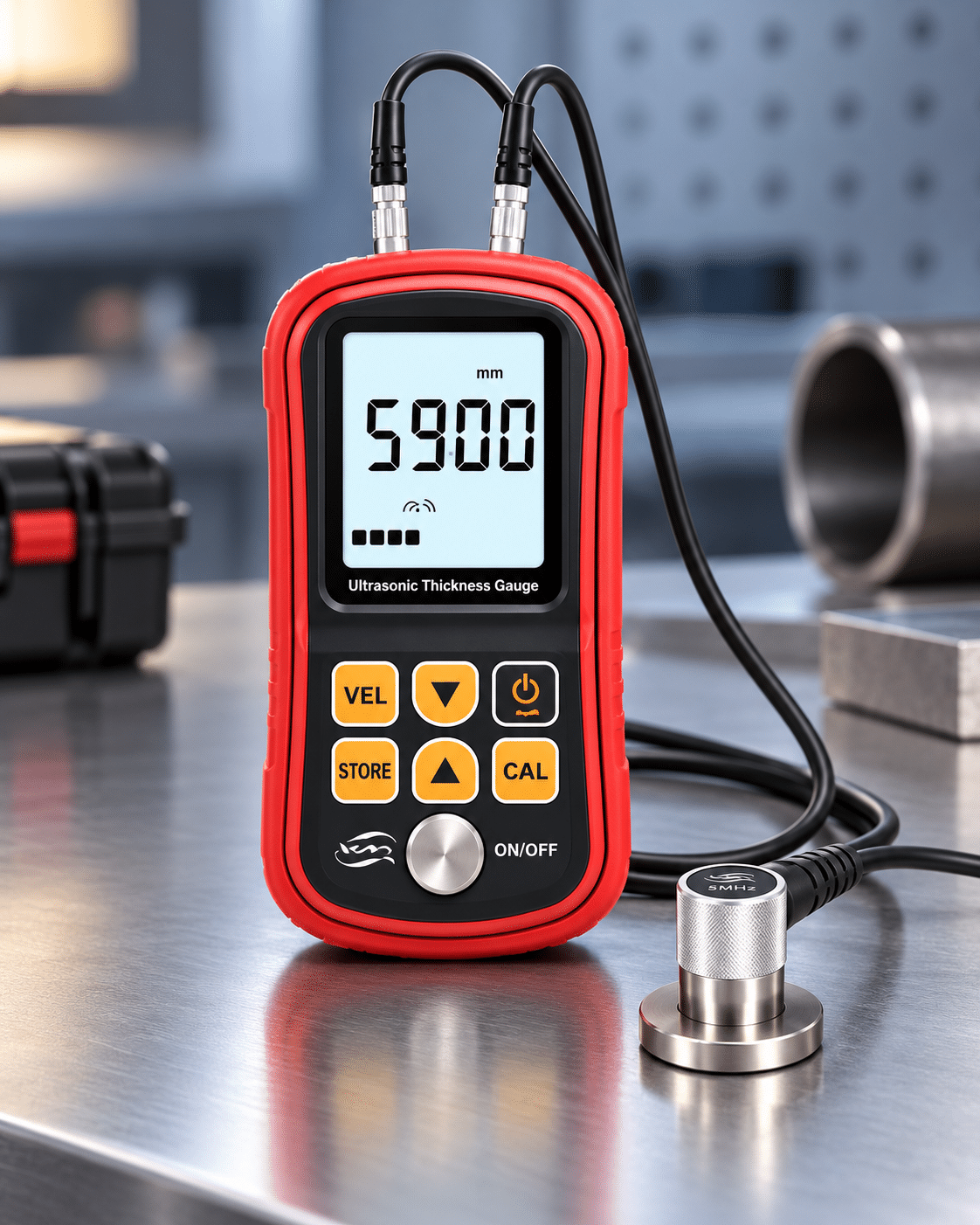
Before critical inspections, operators can perform basic checks to confirm that the gauge and probe work as expected.
For formal calibration, trained technicians should use suitable reference standards and approved procedures.
Follow these steps to check key measurement functions:
1. Clean the Gauge, Probe, and Reference Block
First, clean the probe face, cable connectors, and reference block.
Use a suitable cleaning method to remove dirt, grease, and old couplant.
Next, inspect the probe face for wear or physical damage.
A damaged probe can affect the ultrasonic signal and measurement stability. Therefore, replace or inspect the probe when its condition may affect the test.
2. Check the Probe Zero
Next, connect the probe to the gauge and apply a small amount of suitable ultrasonic couplant to the reference surface.
Then, place the probe on the zero or reference block.
Follow the manufacturer’s procedure to run the probe zero function.
This step helps the gauge account for probe delay and other factors that affect the starting point of the measurement.
3. Set the Correct Material Velocity
After that, select the correct material velocity for the reference material.
For example, a carbon steel reference may use a nominal sound velocity near 5,920 m/s, depending on the material and test method.
However, the correct value depends on the material, temperature, probe, and measurement method.
Therefore, technicians should use the certified value for the reference standard rather than relying on a general material value.
4. Perform Multi-Point Thickness Checks
Then, measure several known thickness steps on a certified reference block.
For example, a 5-step block may include thickness values from about 2.5 mm to 20 mm, depending on the block design.
Record each gauge reading and compare it with the certified thickness.
Next, review the results across the full range.
This process can show whether the gauge maintains consistent accuracy at both thin and thick points.
5. Compare Results With the Required Tolerance
Finally, compare the measured values with the applicable maximum permissible error (MPE) or customer specification.
If the results fall outside the required limit, stop using the gauge for critical inspection.
Instead, check the probe, couplant, material setting, reference block, and gauge setup.
If needed, send the instrument for formal calibration or repair.
3. Daily Check vs. ISO/IEC 17025 Accredited Calibration
Daily Operator Checks vs. ISO/IEC 17025 Accredited Calibration
A daily zero check by a field operator verifies basic functionality prior to inspection. However, daily checks cannot replace formal ISO/IEC 17025 laboratory calibration, which provides certified measurement uncertainty, NIST traceability, and multi-point scope verification.
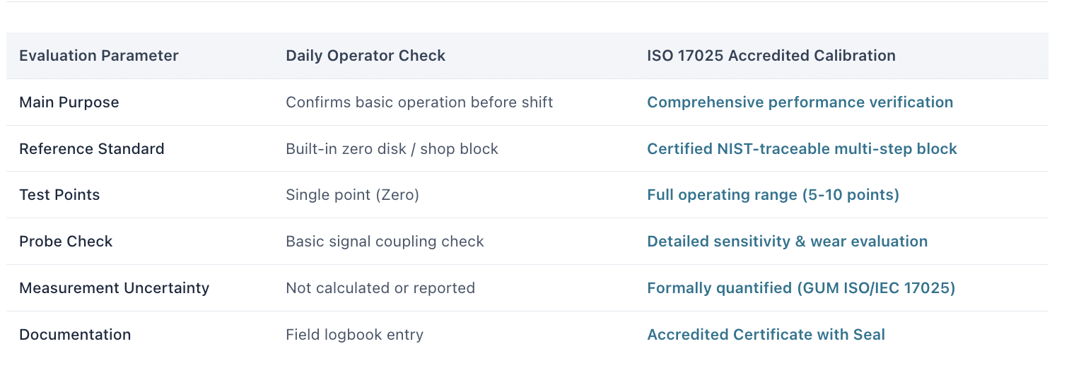
Therefore, operators should use daily checks to confirm readiness. At the same time, they should use accredited calibration to verify measurement accuracy at defined intervals.
4. How Temperature Affects Ultrasonic Thickness Measurements
Temperature can affect ultrasonic thickness readings in several ways.
First, sound velocity changes with temperature. Different materials also respond differently to temperature changes.
In addition, the probe and couplant can behave differently at elevated temperatures.
As a result, a gauge that works well at room temperature may show different results when technicians inspect hot equipment.
Therefore, users should follow the probe and gauge manufacturer’s temperature limits.
For critical work, technicians should also consider the actual part temperature when they set up the measurement.
5. What Is Sound Velocity in Ultrasonic Thickness Testing?
Sound velocity describes how fast an ultrasonic wave travels through a material.
The gauge uses this value to convert ultrasonic travel time into a thickness measurement.
A simple relationship is:
Thickness = Sound Velocity × Travel Time / 2
The gauge divides the result by two because the ultrasonic pulse travels to the back wall and then returns to the probe.
Therefore, an incorrect sound velocity setting can cause an incorrect thickness reading.
For this reason, technicians should use the correct velocity for the material and test conditions.
6. Best Practices for Ultrasonic Thickness Gauge Calibration
Good measurement practice starts before the calibration or inspection begins.
First, keep the gauge, probe, and reference blocks clean.
Next, use suitable and traceable reference standards for formal calibration.
In addition, keep the probe and cable in good condition.
Technicians should also record calibration results and review past data.
For example, repeated calibration results can show whether measurement performance remains stable over time.
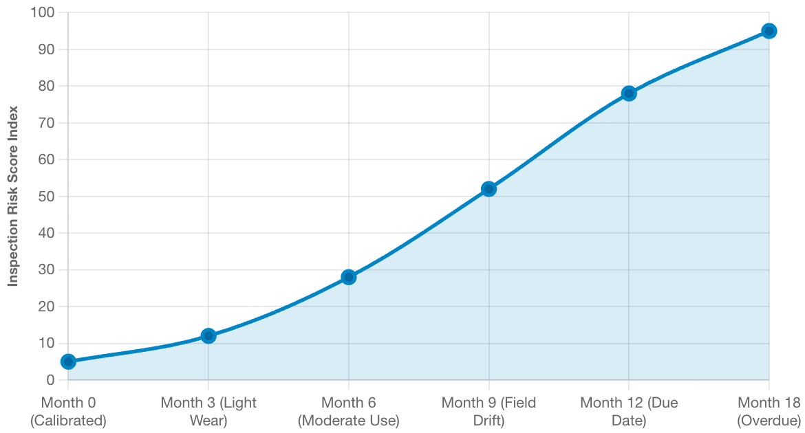
Finally, adjust the calibration interval when equipment use, environmental conditions, or historical results show a higher measurement risk.
Techmaster US: Your Accredited Metrology Partner
Techmaster Electronics, LLC is an ISO/IEC 17025 accredited calibration laboratory (ANAB cert AC-1736) founded in 1989. It serves the United States from five labs (four ISO/IEC 17025 accredited) in Vista CA, Santa Clara CA, Orlando FL, San Antonio TX, and Holly Springs NC, with corporate offices in Vista CA and Henderson NV.
Techmaster US provides calibration services for non-destructive testing equipment, dimensional instruments, precision mass tools, and electronic test equipment.
In addition, Techmaster US offers mobile on-site calibration for supported equipment. This service can help reduce shipping needs and limit production downtime.
Therefore, customers can maintain equipment records and measurement traceability while keeping critical inspection equipment in service.
Frequently Asked Questions (FAQs)
1. What is ultrasonic thickness gauge calibration?
Ultrasonic thickness gauge calibration is the formal process of verifying an NDT instrument’s measurement accuracy against certified, NIST-traceable reference standards. This process ensures the gauge correctly calculates transit time and wall thickness across a specified acoustic velocity range.
2. How often should an ultrasonic thickness gauge be calibrated?
An ultrasonic thickness gauge should receive accredited laboratory calibration every 12 months under normal operating conditions. Instruments subjected to severe industrial field environments, extreme thermal exposure, or continuous daily inspection duty should be calibrated every 6 months.
3. Why is acoustic velocity adjustment critical during calibration?
Acoustic velocity adjustment is critical because sound travels at different speeds through different materials. If the gauge’s programmed velocity does not match the specific alloy being tested, calculated thickness values will contain proportional measurement errors.
4. What is the difference between probe zeroing and full multi-point calibration?
Probe zeroing compensates for the physical delay time of sound passing through the transducer face and couplant layer at a single point. Full calibration tests the instrument’s electronic timing linearity across multiple certified thickness steps to ensure accurate readings throughout its entire operating range.
5. What reference standards are used for ultrasonic thickness calibration?
ISO/IEC 17025 calibration utilizes NIST-traceable 5-step or 10-step reference blocks manufactured from certified materials with known acoustic velocities. Dimensional tolerances of these master step blocks are verified using high-precision mechanical or optical measuring instruments.
6. Can temperature changes cause ultrasonic thickness measurement errors?
Yes, temperature changes alter both sound velocity within the substrate material and the delay time of the transducer. High temperatures reduce sound velocity in metals, causing uncompensated thickness gauges to display artificially thick wall measurements.
Ultrasonic Thickness Gauge Calibration: Step-by-Step Guide
Essential operational metrology for piping, pressure vessels, structural steel, and manufacturing asset integrity. Master sound velocity calibration, probe zeroing, thermal drift compensation, multi-step reference blocks, and ISO/IEC 17025 traceability.
CONTACT USReferences & industry standards
- ISO/IEC 17025 testing & calibration laboratory requirements
- NIST calibration services and measurement traceability
- A2LA / ANAB accreditation for calibration laboratories
External standards bodies. Techmaster Electronics is an ISO/IEC 17025-accredited, NIST-traceable calibration laboratory.
Frequently asked questions
What is ultrasonic thickness gauge calibration?
Ultrasonic Thickness Gauge Calibration is the documented comparison of a ultrasonic thickness gauge against NIST-traceable reference standards under ISO/IEC 17025. It quantifies the ultrasonic thickness gauge’s error and measurement uncertainty and confirms it performs within tolerance, with as-found and as-left data on the certificate.
How often should a ultrasonic thickness gauge be calibrated?
Most quality systems calibrate a ultrasonic thickness gauge every 12 months, or sooner after repair, overload, or before critical measurements. Set your interval from the manufacturer spec and your ISO 9001 / 13485 / AS9100 program and drift history.
Is Techmaster’s ultrasonic thickness gauge calibration ISO 17025 accredited?
Yes. Techmaster Electronics is ISO/IEC 17025:2017 accredited by ANAB (Certificate AC-1736). Every ultrasonic thickness gauge calibration is NIST-traceable and issued with a full measurement-uncertainty budget.
What is the turnaround for ultrasonic thickness gauge calibration?
Standard turnaround is 5 business days, with 1–2 business-day expedite available. On-site calibration removes shipping time entirely for ultrasonic thickness gauges that can’t leave the floor.
Do you calibrate ultrasonic thickness gauges on-site or in-lab?
Both. Techmaster runs five US labs (Vista CA, Santa Clara CA, Orlando FL, San Antonio TX, Holly Springs NC) and offers nationwide on-site ultrasonic thickness gauge calibration to minimize downtime.

Calibration engineer at Techmaster Electronics, ISO/IEC 17025 accredited laboratory with 35+ years of metrology expertise.