
What does an outside micrometer calibration verify?
Micrometers look simple, but they are among the most heavily relied-upon instruments in a machine shop, inspection cell, and aerospace receiving area. A 0–25 mm or 0–1 in. outside micrometer from Mitutoyo, Starrett, Mahr, or Fowler typically resolves 0.001 mm (0.0001 in.) and is used to accept or reject features with tolerances of a few hundredths of a millimeter. Its performance depends on a precision-ground spindle thread, two lapped carbide measuring faces, and a controlled measuring force. Each of those can wear, and each shows up as a different kind of error.
The design and metrological characteristics of this instrument class are defined in ISO 3611:2023, the GPS standard for micrometers for external measurements. It describes the characteristics that matter — error of indication, face flatness, face parallelism, and measuring force — and your calibration procedure should map one-to-one onto them. For the wider family of hand tools, see our guide to ISO/IEC 17025 dimensional calibration.
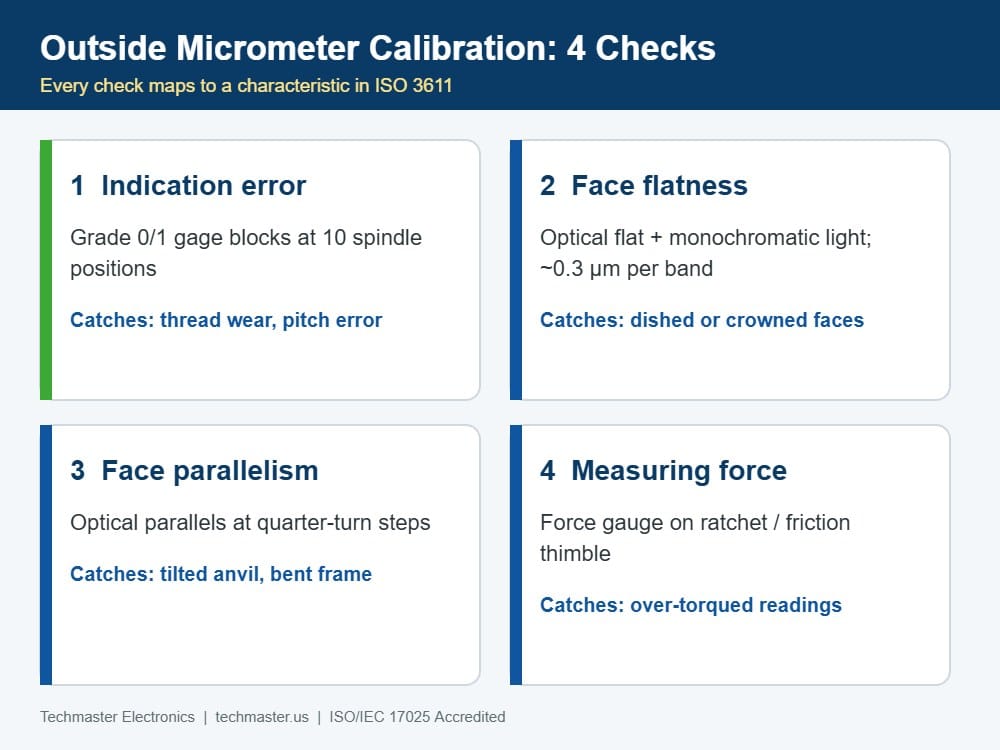
| Calibration check | Reference standard | Failure it catches |
|---|---|---|
| Indication error (linearity) | Grade 0 or 1 gage blocks at ten spindle positions | Thread wear, pitch error, bent spindle, loose nut |
| Measuring-face flatness | Optical flat and monochromatic light, counting interference bands | Dished or crowned faces from wear or a crash |
| Measuring-face parallelism | Set of optical parallels at quarter-turn increments | Tilted anvil, damaged frame, worn faces |
| Measuring force | Force gauge or calibrated load cell | Slipping or missing ratchet that lets operators over-torque the reading |
| Zero / setting check | Setting rod or 0 mm closure (size-dependent) | Zero offset only — does not prove the rest of the range |
Why can a micrometer read zero and still be wrong?
The classic failure is a micrometer that has been dropped or used as a C-clamp. The frame may spring slightly, throwing the faces out of parallel by a few micrometers. Closed together, the faces still touch along a line and the thimble reads zero. Measured across a 20 mm gage block, however, the same tool reads high at one edge and low at the other. In a shop it shows up as parts that “measure good” on the floor and fail at the customer’s CMM.
That is also why a bare “calibrated” sticker is not an adequate record. Auditors under AS9100, IATF 16949, and ISO 13485 expect to see as-found data, because without it you cannot decide whether parts measured since the last calibration are suspect. We explain that logic in as-found vs as-left calibration data and the follow-on process in reverse traceability and recall impact analysis.
How are anvil flatness and parallelism checked?
Optical parallels are glass discs, lapped so their faces are parallel to a fraction of a micrometer, and are supplied in sets whose thicknesses differ by a quarter turn of the micrometer screw (for example 12.00, 12.12, 12.25, and 12.37 mm). Measuring all four means the faces are sampled at four angular positions of the spindle, so a parallelism fault is separated from a thread fault. The number of fringes visible on the parallel’s face also shows whether the anvil is flat or tilted.
Because the calibration depends on reference artifacts that are themselves calibrated, the traceability chain matters. Our article on primary, secondary and working standard hierarchy shows how gage blocks, optical flats, and parallels link back to the national length standard that NIST’s Dimensional Metrology Group maintains and disseminates.
Which gage block points should you use for linearity?
A micrometer with a 0.5 mm pitch screw completes one revolution every 0.5 mm. If you test only at 5, 10, 15, 20, and 25 mm, every point lands at the same angular position of the thimble, and a periodic pitch error hides completely. Offsetting each point by a fraction of a revolution samples the full thread cycle. The gage blocks themselves are normally Grade 0 or Grade 1 per ISO 3650 — the foundation of micrometer calibration with gage blocks; see our gage block calibration guide for how those reference blocks are certified.
| Range | Typical gage block / reference points (mm) | Setting standard |
|---|---|---|
| 0–25 mm | 2.5, 5.1, 7.7, 10.3, 12.9, 15.0, 17.6, 20.2, 22.8, 25.0 | Closed faces (zero) |
| 25–50 mm | Same offset pattern repeated across the 25 mm span, with both end points included | 25 mm setting rod |
| 50–75 mm and above | Representative points across each 25 mm span; end points always included | Setting rod matched to range |
Digital micrometers calibrate the same way. The same discipline also underlies digital caliper calibration and bore gage calibration, where a slide or a transfer mechanism replaces the screw.
What accuracy and test uncertainty ratio should you expect?
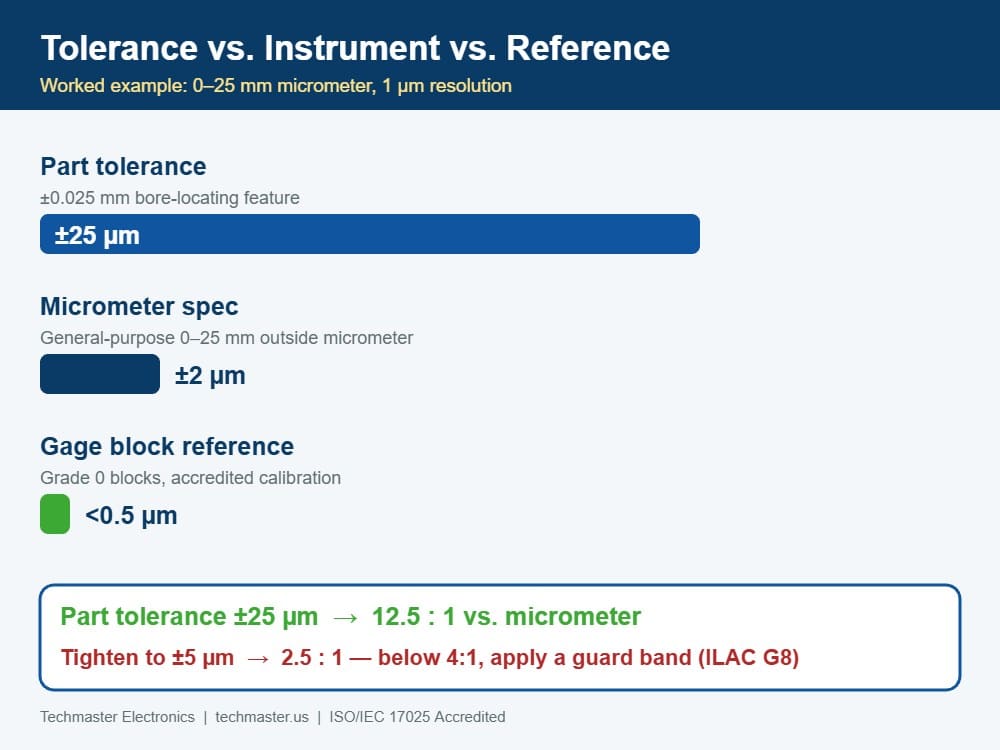
Take a worked example. A shop machines a bore-locating feature at 25.00 mm with a ±0.025 mm (±25 µm) tolerance and checks it with a 1 µm-resolution micrometer specified at ±2 µm. The tolerance-to-instrument ratio is 12.5:1 — comfortable. Tighten the tolerance to ±0.005 mm and the ratio falls to 2.5:1: at that point the micrometer’s error and the calibration uncertainty consume enough of the band that the shop needs a guard band or a better instrument. The rules for doing that correctly are in our guides to test uncertainty ratio and decision rules and guardbanding explained, and they follow ILAC G8, the guidelines on decision rules and statements of conformity.
Measurement uncertainty in a micrometer calibration includes the gage block uncertainty, the temperature difference between the block, micrometer, and the room, thermal expansion of the steel frame, the resolution of the thimble, and repeatability across several closures. Steel expands roughly 11.5 µm per metre per °C, so holding a 25 mm block in a warm hand for a minute can add a measurable error. Accredited labs control this with a soak period and a temperature-stable room; see how calibration lab temperature and humidity are controlled.
How often should micrometers be calibrated?
The interval is a risk decision, not a calendar habit. Techmaster has been calibrating dimensional instruments since 1989, and across the 381,916 calibrations in our 10-year service dataset, hand tools that are heavily shared between operators are consistently the ones that go out of tolerance first. Your own history is the best predictor: if a micrometer is in tolerance at three consecutive calibrations with small drift, extend; if one fails as-found, shorten. The ILAC-G24 approach is covered in how to set calibration intervals, and cheap between-calibration verification with a gage block or setting rod is covered in intermediate checks between calibrations.
Techmaster Electronics is an ISO/IEC 17025 accredited calibration laboratory (ANAB Cert. AC-1736) with accredited labs in Vista CA, Santa Clara CA, Orlando FL, and San Antonio TX. Our ISO/IEC 17025 calibration services cover 12 disciplines, so micrometers, calipers, gage blocks, and the electronic test equipment on the same shop floor can ride on a single quote and a single set of traceable certificates.
Key takeaways
- A micrometer that reads zero can still be wrong at other positions: calibration must check linearity, flatness, parallelism, and measuring force.
- Use ten gage block points with non-round values (2.5, 5.1, 7.7 … 25.0 mm) so every thread phase is sampled.
- Optical flats count flatness in interference bands of about 0.3 µm; optical parallels at quarter-turn steps separate parallelism from thread error.
- Compare the certificate uncertainty with your part tolerance — a ratio below 4:1 calls for guard banding under ILAC G8.
- Calibrate every 12 months, retain as-found data, and pull any dropped micrometer from service immediately.
Frequently asked questions
How do you calibrate an outside micrometer?
Calibrate an outside micrometer by measuring gage blocks at about ten positions across its range, checking the flatness of each measuring face with an optical flat, checking parallelism with optical parallels, and verifying the ratchet measuring force. Results are recorded as found and as left, with measurement uncertainty, against the manufacturer specification.
How often should a micrometer be calibrated?
Every 12 months is the standard starting interval for shop-floor micrometers. Shorten it to six months for tools used on abrasive materials or shared by many operators, and extend it only after consecutive in-tolerance as-found results support a longer interval under an ILAC-G24 style review.
Why are gage block points like 2.5 mm and 12.9 mm used instead of round numbers?
A micrometer screw has a 0.5 mm pitch, so round-number blocks all land at the same thimble position and hide periodic screw error. Offset values such as 2.5, 5.1, 7.7, and 12.9 mm test different angular positions of the spindle and reveal pitch variation across a full revolution.
What is the accuracy of a typical outside micrometer?
A general-purpose 0–25 mm outside micrometer is typically specified at about ±2 µm, and high-accuracy models at about ±1 µm. Always use the specification published for your exact model, because accuracy grows with range and differs between brands and digital versus vernier types.
Does a micrometer need ISO/IEC 17025 accredited calibration?
If your quality system or customer requires traceable measurements, yes. An accredited certificate documents traceability to national standards, reported uncertainty, and as-found data, which auditors in aerospace, automotive, and medical device manufacturing commonly expect.
Can a dropped micrometer still be used if it reads zero?
No. A drop can bend the frame or tilt the anvil so faces touch at zero but are no longer parallel. Remove the micrometer from service and have it verified for linearity, flatness, and parallelism, then review measurements made since its last good calibration.
Get micrometer calibration you can defend in an audit
ISO/IEC 17025 accredited dimensional calibration with as-found/as-left data and reported uncertainties — from the accredited calibration laboratory trusted by US manufacturers since 1989.
Request a Calibration Quote
Khanh Nguyen is the Marketing Manager at Techmaster Electronics, a B2B marketing leader covering the test, measurement, and ISO/IEC 17025 accredited calibration industry in the United States.